What Is Chageover Switch? Let Us Take A Look At Its Fuctions And Applications.
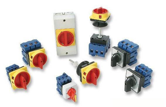
The main function of the cam universal conversion switch is to convert the current, and this kind of switch use is quite common. The universal transfer switch needs to be operated properly, otherwise it is prone to circuit failure. The use of this switch has conditional restrictions, to the surrounding environment requirements are more strict, can not be used in the ultra-high temperature or ultra-low temperature environment, otherwise it will damage the switch. Next, xiaobian to take you to understand how to operate the universal conversion switch.

How does the cam universal converter switch operate
1. Use the handle to drive the rotating shaft and cam push contacts to be on or off. Due to the different shape of the cam, the coincidence situation of the contact is different when the handle is in different positions, thus achieving the purpose of the conversion circuit.
2. Common products include LW5 and LW6 series. The LW5 series can control small capacity motors of 5.5kW and below; the LW6 series can only control small capacity motors of 2.2kW and below. When used for reversible operation control, a reverse start is allowed only after the motor has stopped. LW5 series universal converter switch can be divided into self-duplex and self-positioning mode according to the handle. The so-called self-duplex is to use the handle in a certain position, the hand release, the handle automatically return to the original position; positioning refers to the handle is placed in a position, can not automatically return to the original position and stop in the position.
3. The handle operation position of the universal transfer switch is indicated by an Angle. The handles of different models of the universal converter switch have different contacts of the universal converter switch. The graphic symbols in the circuit diagram are shown in the figure below. However, since the engagement state of the contact point is related to the position of the operating handle, the relationship between the operating controller and the engagement state of the contact point should also be drawn in the circuit diagram. In the figure, when the universal converter switch hits left 45°, contacts 1-2,3-4,5-6 close and contacts 7-8 open; at 0°, only contacts 5-6 are closed, and at right 45°, contacts 7-8 are closed and the rest open.
How to connect the universal converter switch
1. The LW5D-16 voltage conversion switch has a total of 12 contacts. Facing the front side of the switch, the switch is divided into the left and right four w positions. Panel indicates 0 top, neutral, AC left, AB right and BC bottom. Behind the panel is the terminals. Also divided into up and down around. Let’s talk about it first.
2. The left 6 terminals have been connected to the factory, from the front to the back, respectively, top 1, bottom 3 is the first group, phase A, top 5, bottom 7, group 2, phase B, top 9, bottom 11, group 3. The first contacts contact A, the second contacts connect B and the third contacts C.approach.1.3,5.7,9.11 to ABC three-phase.
3. The six terminals on the right are separated up and down, but the top and bottom of the front and rear terminals have been connected respectively. That is, 2,6,10 are the first set of contacts 4,8,12 are the second set of contacts below. That is, 2.6.10 and 4.8.12 connect to the voltmeter. These two sets of contacts are the two lines of voltage connection voltage voltmeter over the two can be arbitrarily connected to these two points, these two points are no sequential points.
4. When the switch handle turns to indicator 0, all terminals are in an open state and no contact is on. When the switch handle to the indicator AB phase, the left front top 1 terminal A terminal and right front first terminal and above 2 points, namely 1,3 end and 2,6,10 end interlinked, at the same time, the left second row, the lower point 7 of B terminal and the right same bottom point 8 connectivity, namely, 5,7 and 4,8,12, from 2,6,10 and 4,8,12 terminals, forming a line voltage loop. This one can be seen clearly when you get the switch. The same reason explains the circuits of AC and BC, respectively.
We have been manufacturing and supplying equipment in an emerging market for CAM switch.
Post time: Dec-02-2022


